MULTIFREQUENCY RF FRONT END SYSTEMS
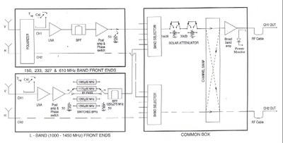
Giant Meter-wave Radio Telescope (GMRT) Front Ends have been designed to operate at 5 frequency bands centered at 50 MHz, 150 MHz, 235 MHz, 327 MHz, 610 MHz and L-Band extending from 1000 to 1450 MHz. The L-Band is split into four sub-bands centered at 1060 MHz, 1170 MHz, 1280 MHz and 1390 MHz, each with a bandwidth of 120 MHz. ?The 150 MHz, 235 MHz and 327 MHz bands have about 40 MHz bandwidth and the 610 MHz band has about 60 MHz bandwidth. The low noise front end of the receiving system of GMRT has been designed to receive dual polarization. Lower frequency bands from 150 to 610 MHz have dual circular polarization channels (Right Hand Circular and Left Hand Circular polarization) which have been conveniently named as CH1 and CH2, respectively. The higher frequency L-Band has dual linear polarization channels (Vertical and Horizontal polarization) and they have been named CH1 and CH2 respectively. The front end system has flexibility to be configured for either dual polarization observation at a single frequency band or single polarization observation at two different frequency bands. The polarization channels can be swapped whenever required. For observing strong radio sources like "sun", the selectable solar attenuators of 14 dB, 33 dB or~ dB can be used. The front end has RF termination facility also. Any band of the receiver can be switched OFF, whenever not in use, with the RF on/off facility provided in the front end. The receiver can be calibrated by injecting one of the four levels of calibrated noise, named Low cal, Medium cal, High cal and Extra-high cal depending upon the flux density of the source being observed. To minimize cross coupling between channels, a phase switching facility using walsh functions has been provided in the post unit. The functional schematic of the front end system is as shown in figure-1.
Figure -1: Functional schematic of the front end systems (Click to enlarge)
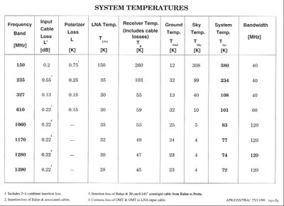
The low noise amplifiers (LNA) for all the frequency bands are un-cooled. At 150 MHz band, Silicon Bipolar MMIC amplifier of Agilent Technologies has been used to design the LNA. The 235 MHz, 327 MHz and 610 MHz, the LNA designs are based on GaAs MESFETS from Agilent Technologies. For the L-Band LNA design, High Electron Mobility Transistors (HEMT) of Fujitsu have been used. For RF switching applications like band selection, RF on/off etc GaAs MESFET MMIC switches have been used. For polarizer designs, WIRELINE Quadrature hybrids of SAGE Laboratories make have been used for 150 MHz, 235 MHz and 327 MHZ bands. The 610 MHz band polarizer has been designed using Branchline Quadrature hybrid. Table -1 summarizes system noise temperatures for different frequency bands.
Table 1: System Temperatures (Click to enlarge)
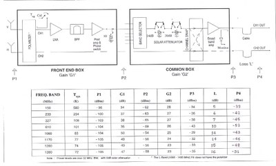
The RF power levels at various stages of the front ends are as shown in figure -2.
Figure 2: RF Power levels (Click to enlarge)
Figure 3 to figure 10 shows the detailed block diagrams of front ends of various frequency bands.
- Figure 3 150 MHz FES
- Figure 4 233 MHz FES
- Figure 5 327 MHz FES
- Figure 6 610 MHz FES
- Figure 7 1060 MHz FES
- Figure 8 1170 MHz FES
- Figure 9 1280 MHz FES
- Figure 10 1390 MHz FES
Persons to contact
Document Actions


