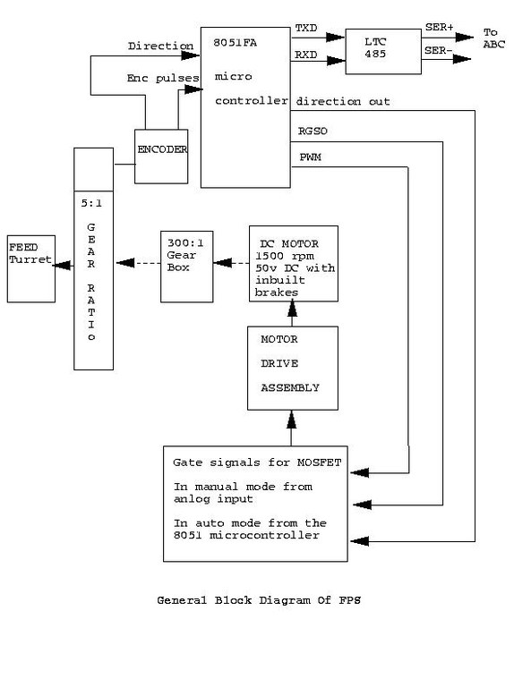
Block Diagram and Description
The feed drive circuit consists of a half HP DC servo motor with brakes.This is driven by power MOSFETS.An 'H' configuration is used to enable bidirectional rotation.Hence at a time two diagonally opposite MOSFETs are switched ON.The speed of the motor is controlled using Pulse width Modulation technique. The PWM is generated by 8051 based microcontroller.The appropriate software produces the trapezoidal speed profile for achieving high accuracy of 1.054 arc min. The microcontroller also facilitates communication with control room using RS485 protocol.
The feed rotation is restricted to 275 deg. as feed cable wrap hose carries the front end,RF Control and Monitor cables. End limit switches are provided at -15 deg. and 285 deg. along with stoppers for ensuring safety from over travel of feed turret.
A CAL switch is provided at 275 deg.for calibration of the incremental encoder.There is a further facility to check the encoder value using the internal marker UA0. A current limit circuitry is provided to limit armature current to 12 amp. which is the maximum rating of the drive motor. The NVRAM IC DS1220Y is provided to retain the current position in case of power failure and thereby avoiding frequent recalibration. Manual rotation is facilitated from antenna base .LCD is provided in the electronics unit at the base (to be implemented) for ease and accurate rotation of feed from the antenna base.
The block diagram for FPS system is as shown in fig :

The feed drive motor is coupled to the feed turret through two stages of gear reduction,first is a worm gear with 300:1 reduction and the second one is primary bull gear with 5:1 reduction, Thus total gear reduction is 1500:1. The incremental encoder is used for marking the position. As shown in the figure the encoder is connected to the output shaft of the worm gear reduction .This means that for one complete rotation of the turret,the encoder rotates for 5 times.Encoder gives the direction and count signals which act as a position feedback to 8051FA microcontroller.The CPU card is based on 8051FA microcontroller. 8051 has inbuilt serial port through which it communicates to the antenna base computer through RS485 link.Microcontroller 8051FA gives the command signals like direction, RGSO and PWM to the drive card which drives the MOSFET bridge to rotate the motor in the proper direction and set speed and thus feed is focussed with an accuracy of one arc minute pointing.
Due to the above bull gear and gear box arrangement of the feed ,when feed completes one rotation (rotation through 360 degrees) ,encoder goes through five rotations. The encoder generates 4096 pulses during one complete rotation.thus a complete rotation by feed system will generate 20480 encoder pulses .One pulse from the encoder thus corresponds to 0.0175-degree rotation of the feed(i.e approximately one arc minute).
These encoder pulses are counted by the microcontroller to determine the angular displacement of the feed system .
1 rotation of encoder = 4096 pulses 5 rotations of encoder = 20480 pulses 1 rotation of feed = 5 rotations of encoder 360 deg rotation of feed = 20480 * 2 pulses from encoder
1 pulse = 360 / (20480 X m) where , m = multiplication factor(implemented in software) = 2 1 pulse = 1.054 min Thus feed can be focussed with the resolution of 1.05 min, theoretically.
Document Actions
