Backend System
Our Team:
Ajit Kumar (Group Co-ordinator)
| Analog | |
| Sweta, Gupta. | Hande, P. J. |
| Shinde, N. D. | Nanaware, D. K |
| Phakatkar, S. V. | |
| Atul Ganla |
| Digital | |
| Sandeep Choudhari | Shelton, G. H |
| Harshvardhan Readdy | Mekhla, Mule |
| Halagalli, I. | Buch, Kaushal |
| Bhonde, I. S. |
| Computer, RFI and Other Activities | |
| Joardar, S. | Yogesh Gaikwad |
| Mangesh Umbarje. | Sumit Mirajkar |
Upgrade Plan:
Analog Processing of the RF signals from antenna received at Central Electronics Building. Convert the Analog signals so that it can be digitised and further processing can be done. Digitise the RF signals to get a 400 MHz bandwidth from each polarisation channel. Process the signals to produce interferometry and array outputs.
Block Diagram:
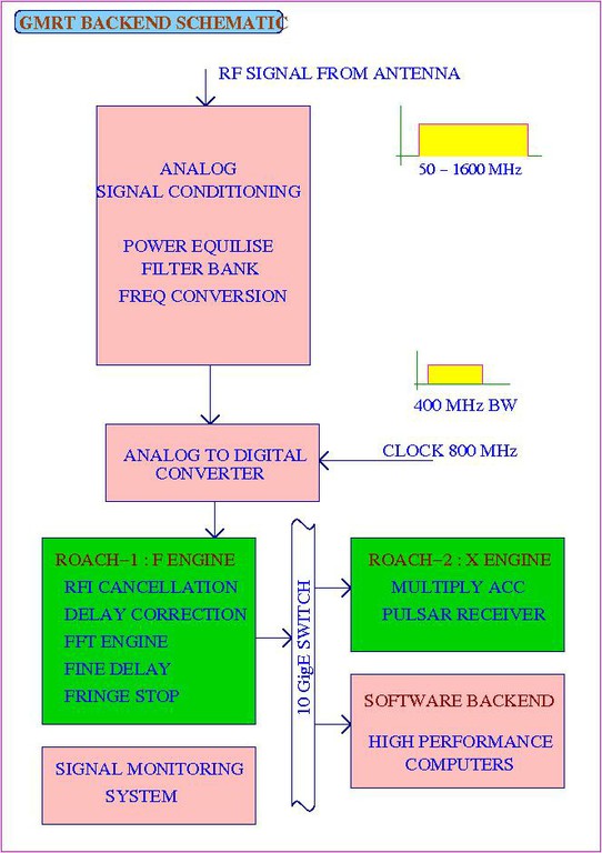
1. GMRT Backend Schematic:

System Specifications:
Analog System :
Input Freq : 30 - 1600 MHz
Input Power : -24 dBm
Max Bandwidth : 400 MHz
Headroom : 27 dB
Output power : -12 dBm
Noise Contribution to FE < 0.01 K
Filter bank – 7 filter selection
1 BB converted signal
Power detector at input and output
Noise + CW cal signal at input
Noise (var corr) cal at ADC input
Digital System :
ADC No. of Bits : 8 bits
Inst Bandwidth : 400 MHz
FFT No. of Channels : 8 K
Mode Available : Full polar
Coarse and Fine Delay correction
Fringe rotation
Interferometer with dump times ~ 100 ms
Incoherent and Phased array beam outputs : at least 2 beams for each; with full time
resolution
Pulsar back-ends attached to the beam outputs
Document Actions

