There are various commands to be issued from user to control the feed rotation in the desired manner. Run commands are used to rotate the feed while set commands are used to set the FPS parameters for run commands and read commands are used to read the set FPS parameters.
RUN COMMANDS are used to rotate the feed in desired direction,by desired count and in desired manner by setting various FPS parameters.
Following are RUN commands used to rotate the feed:
- Run to Calibrate:
This is always the first command to be issued .It forms the part of the calibration process. When issued it causes the feed to move towards the 270 deg limit switch .When the feed hits the 270 deg limit switch ,the rotation is stopped and the current encoder count is initialized to 17000.
- Preset Run Command:
Using the preset run command the feed can be rotated to the target encoder count .This can used only after calibrating the feed i.e when feed is calibrated and idle.This command will get rejected if The target encoder count entered is less than the minimum angle or more than the maximum angle.
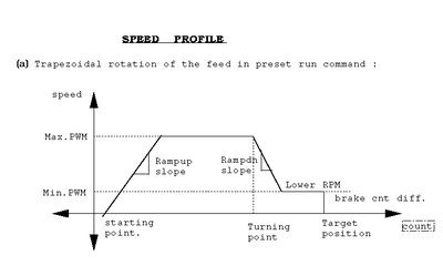
The trapezoidal profile followed by preset run command is as in fig.2

-
The speed begins to ramp up from the starting point until it reaches to the maximum PWM where it remains constant till the turning point difference is reached.When the turning point difference is reached, the speed begins to ramp down till lower RPM reaches.Once the lower RPM is reached , speed remains constant till it reaches the brake count difference,Then the brakes are applied at the target position.
- Run To UA0:
As the motor shaft rotates the encoder generates two incremental square wave signals UA1 and UA2.Once every rotation ,it also generates a square wave pulse called UA0.A UA0 pulse occurs after every one rotation.This pulse can be used as the most accurate reference to calibrate the feed position.
This command is used to search the UA0 pulse in both direction.This command forms the part of the calibration process.the feed rotates in the specified direction till the UA0 pulse occurs.When UA0 is found the PWM is made zero percent and brakes are applied.
- Fine Tune
This command is used to rotate the feed through small amount of counts generally less than 200 counts i.e this command gets executed only when the difference between the current and target encoder count is less than 200 counts.
Set commands as follows:
- Null Command This command is a general purpose command used to communicate with the FPS hardware.
- Set Turning Point Turning point difference is the difference between the current position and target position at which the rpm of the feed starts ramping down.
- Set Ramp Down Time Count: Once the turning point is reached, motor rpm has to be reduced with a uniform rate. This rate can be specified by issuing this command .The motor rpm is controlled by pwm register of 8051.The Ramp Down Time Count is nothing but the time difference in milliseconds after which the count in pwm register is incremented by one to decrement the duty cycle and hence the rpm.
- Set Lower RPM Limit: This command is used to set the lower limit of the motor rpm when it is ramping down. Once the pulse count lower rpm limit reached , further decrement in rpm is stopped.
- Set Brake Count Differance: Brake count difference is the difference between current angle and the target angle at which brakes should be applied.
- Set Ramp Up Time count: As feed starts rotating ,it is not wise to increase the rpm to its maximum allowed value .This transition in the count can be made smooth by decrementing count in the pwm register of 8051 microcontroller at regular interval.Set ramp up time count command is used to specify this time.
- Set Stop Time Count: This is the rate at which the pwm register count is incremented by one when a stop command is issued by user.
- Set Max PWM Count: This command controls the maximum rpm of motor that can be achieved in any run command. Argument to this command is a byte that is nothing but the minimum value in hex in the PWM register.
- Set Max Angle: As the feed starts moving towards 270 deg. limit switch angle count goes up.Upper limit on this angle is set up by this command so that software does not allow the feed to cross this limit.
- Set Minimum Angle: Similarly ,as feed moves toward -15 deg. limit switch angle count goes down.This command is used to set the lower limit on the minimum angle position that feed can attain.
READ COMMANDS are used to read all FPS parameters that can be set using set commands can by usibg the respective READ commands.

