Plan Meetings
Our Team: 1. G. Sankarasubramanian (Group Coordinator) 2. Hanumanth Rao Bhandari
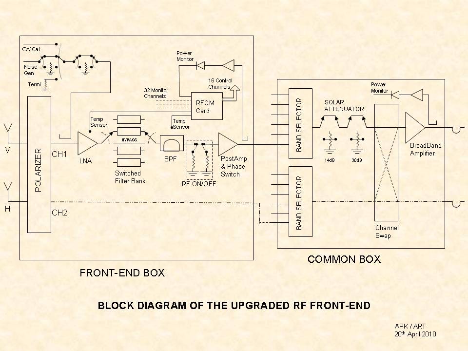
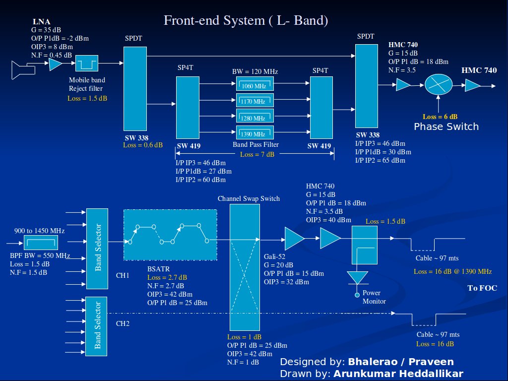
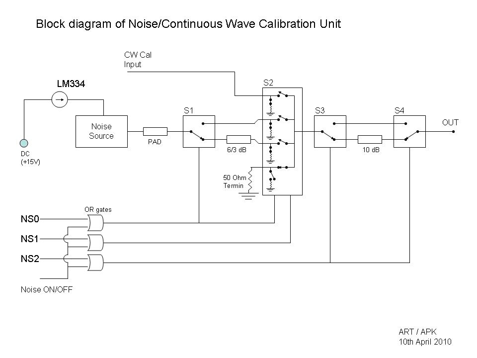
Block Diagram:
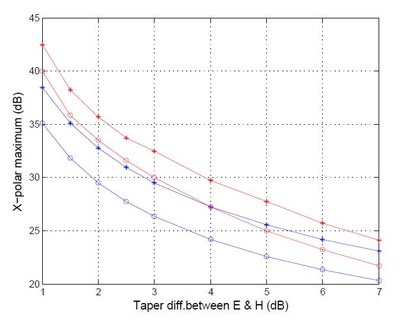
1. Tapper Vs. Crosspolar:
Reports:
Simulation of Pair of 150MHz Thick Folded Dipole Using WIPL-D 3D EM Solver
A Report on Accuracy between Feed Simulations and Measurements
NCRA Test Range - An Estimate of Ground reflections
The NCRA Test Range for Wide-band Feeds Development (under XI Plan)
Presentation:
Our Team: A. Praveen Kumar (Group Coordinator) 1. Anil Raut 2. Bhalerao, V. B. 3. Ramesh, S. 4. Manisha Parathe 5. Arati Sandikar
Reports:
Our Team :S.Sureshkumar, Pravin Raybole, Arun Kumar, M. Gopinathan, Satish Lokande, Digambar
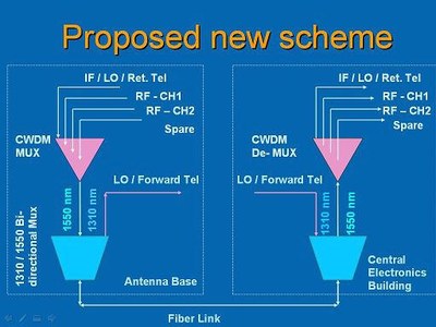
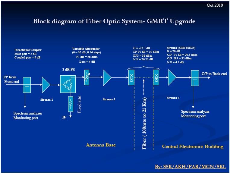
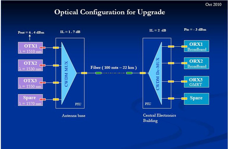
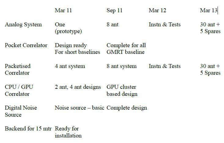
Upgrade Plan
- Broadband analog fiber optic link GMRT Upgrade.
- Ethernet link to antennas 1 Gbps.
- Supporting existing fiber optic link with smooth upgrade.
- 8 x 1 GBE Long haul fiber optic link
- Fiber Optic LAN for GMRT Fiber to your work place.
- RF common box with fiber connectivity 15 meter dish.
Our Team:
Ajith Kumar (Group Co-ordinator)
| Analog | |
| Sweta, Gupta. | Hande, P. J. |
| Shinde, N. D. | Nanaware, D. K |
| Phakatkar, S. V. | |
| Atul Ganla |
| Digital | |
| Sandeep Choudhari | Shelton, G. H |
| Harshvardhan Readdy | Mekhla, Mule |
| Halagalli, I. | Buch, Kaushal |
| Bhonde, I. S. |
| Computer, RFI and Other Activities | |
| Joardar, S. | Yogesh Gaikwad |
| Mangesh Umbarje. | Sumit Mirajkar |
Upgraded Plan :
Analog Processing of the RF signals from antenna received at Central Electronics Building. Convert the Analog signals so that it can be digitised and further processing can be done. Digitise the RF signals to get a 400 MHz bandwidth from each polarisation channel. Process the signals to produce interferometry and array outputs.
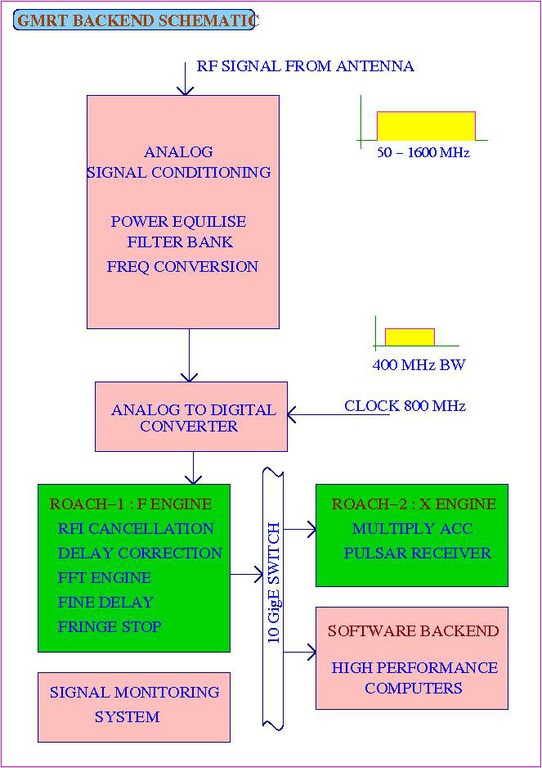
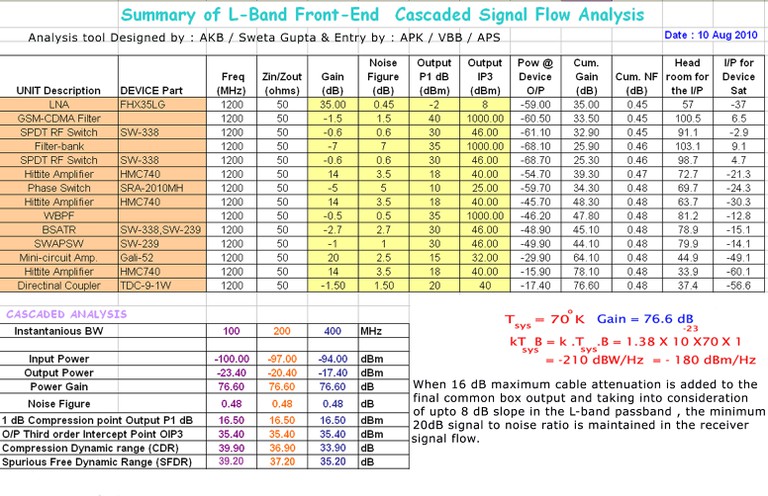
System Specifications:
- Analog System :
- Input Freq : 30 - 1600 MHz
- Input Power : -24 dBm
- Max Bandwidth : 400 MHz
- Headroom : 27 dB
- Output power : -12 dBm
- Noise Contribution to FE < 0.01 K
- Filter bank – 7 filter selection
- 1 BB converted signal
- Power detector at input and output
- Noise + CW cal signal at input
- Noise (var corr) cal at ADC input
- Digital System :
- ADC No. of Bits : 8 bits
- Inst Bandwidth : 400 MHz
- FFT No. of Channels : 8 K
- Mode Available : Full polar
- Coarse and Fine Delay correction
- Fringe rotation
- Interferometer with dump times ~ 100 ms
- Incoherent and Phased array beam outputs : at least 2 beams for each; with full time
- resolution
- Pulsar back-ends attached to the beam outputs
Our Team
| R.Balasubramaniam | Group Co-ordinators |
| Dr. Ishwar Chandra Dr.Nimisha Kantharia | Academic Co-ordinators |
Telemetry Group
| Jitendra Kodilkar | Charudutta Kanade |
| RajuUprade | Naresh Sisodiya |
| C. Satheesh | Mayur Sutar |
| Mahadev |
Planned activities for 2010-11:
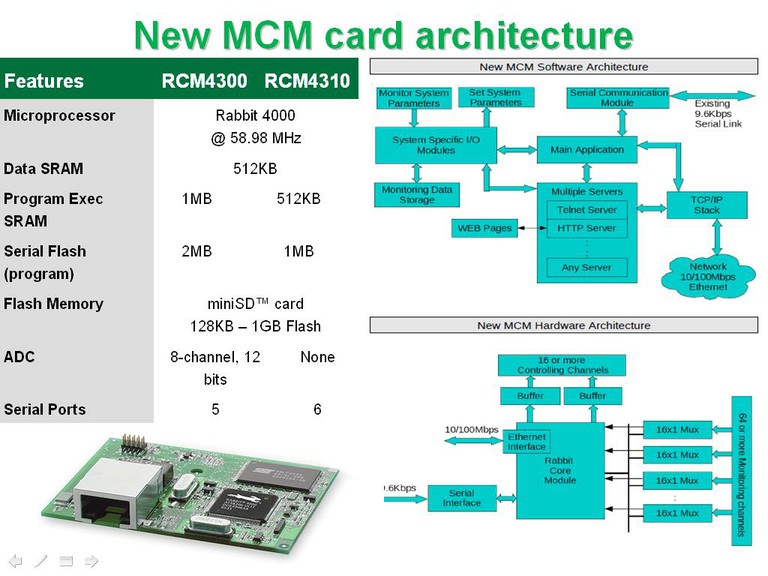
- Modification of software to Control MCMs and SERVO system through Ethernet C Commn.
- Design and development of user-friendly GUI.
- Development of improved user-friendly TeleDisp to show antenna status.
- Interaction with other systems like Baseband, Data acquisition, Correlator and Pulsar ?
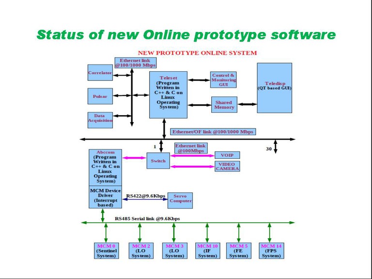
Present Status:
- Successfully ported TeleSet, AbcCom, TeleDisp & MCM driver to FC9 from FC3.
- The response time of the Status in from the antennas is reduced considerably.
- Multi-user and Multi-sub array feature added to the software.
- Automation of MCM device driver insertion in Kernel.
- Modified software has been tested successfully in C00, C04 and C12 antennas to Control and Monitor thro' 100 Mbits/sec Ethernet
- Communication, ABR, FPS, Servo and Sentinel systems. Live demonstrations were shown to LFRU and HPC conference participants.
- Successfully tested Servo system thro' USB to the Serial port adaptor.
- Development of device driver to Control MCM thro' standard USB to Serial port adapters.
Update Soon...